Chapter 12: Analog approaches, non-linear editing, and compositing
12.2 ANIMAC / SCANIMATE
Perhaps one of the earliest pioneers of this analog computer animation approach was Lee Harrison III. In the early 1960s, he experimented with animating figures using analog circuits and a cathode ray tube. Ahead of his time, he rigged up a body suit with potentiometers and created the first working motion capture rig, animating 3D figures in real-time on his CRT screen. He made several short films with this system, which he called ANIMAC.
Harrison studied at the School of Fine Arts at Washington University in St. Louis. After a stint in the Coast Guard, he joined McDonald Aircraft in St. Louis as a technical illustrator. He returned to Washington University to study engineering, and took a job as an engineer at Philco Corporation in Philadelphia and later as a bio-cybernetic Engineer at the Denver Research Institute at the University of Denver.
It was while he was at Philco that he decided to chase his idea of systematically creating animated figures. His concept was to view a stick figure as a collection of lines that could be independently moved and positioned to form an animated character. Each of the lines would be displayed on a CRT and controlled with a vector deflection of the CRT’s electron beam. Each figure would be composed of bones, skin, joints, wrinkles, eyes, and moving lips, all drawn in sequence to create what Harrison called a “cathode ray marionette.”
In order to accomplish this task, he founded a company in Philadelphia called Lee Harrison and Associates. His ideas were realized with a hardware system designed and developed by his new company, which he called called ANIMAC. Harrison participated in the Ars Electronica Festival, along with computer video artists Bill Etra and Bill Diamond and others, in 1992. A facsimile, entitled Notes for an Early Animation Device in which the design and operation of ANIMAC was described, is included in the archives of the Festival. The following is from an interview with Jeff Schier, also published in the Festival proceedings:
“WE STARTED OUT by developing what later became ANIMAC. At first we called our machine “The Bone Generator” because it made sections of straight lines that could be hooked together and could be individually animated or moved in three dimensional space. To determine what a bone was you had to determine where it was to start in X, Y, Z space, in which direction it went from there, and for how long, in order to determine its length. The parameters that determined which direction it was going in also determined the actual length projected onto the face of the tube. If you saw a bone from the side you saw its full length but if it were pointing toward you, you saw only a portion of it.
A bone was composed of a bi-stable multi-vibrator or a flip-flop. To start it was to essentially put a signal on a line that governed the opening of a lot of sampling gates. The inputs to the gates were the parameters that governed the position and some of the qualities and characteristics of that bone. To program it we had a patch panel.We always had a navel point on our figures and we’d always flip back to the navel point. We’d go up and out an arm and go back to the navel point, go up and out another arm and back to the navel, go up and out to the head. Those were all fly-back bones and we would fly-back by just collapsing the information that was contained on a capacitor.
In order to determine the length of a bone we used time as the basis. We’d start drawing in a certain direction determined by the specific parameters and we’d go in that direction until we’d turned that bone off and then essentially we’d wait there until we drew another bone. The length was determined by plugging a timing circuit into a place which was reset after each bone. When you started a bone you also started that counter and that flip-flop was plugged into the counter that would turn that bone off. It was pretty much all digital. The next bone would be plugged into another count and so forth and you varied the counts depending. A count represented some number of high frequency units that was part of the clock network of the whole machine.
The patch panel was color-coded and it was a big patch panel we got out of the junkyard someplace. If you understood the code you could actually see the bones on this patch panel. There would be a certain color like green and the output might be a blue. If you were going to bone number one, you brought a start pulse that was located somewhere and you’d plug into the first bone and then you’d plug in the output of the first bone into the second bone and so forth. The inputs to the parameter gates were not located on that panel. They were located down a little lower on the face of the Animac and there were hundreds of them. You had all of these hundreds of inputs required to make the thing happen and to change it over time. After this, the main thrust of our development was to make things change over time which eventually culminated in what we called key frame programming where we would turn knobs until we got what we wanted.”
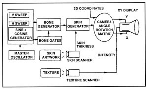
The “skin” was added to the bones by superimposing “springs” that modulated the stick vectors with circular sweeps of spinning vectors. The thickness of the bones, or displacement of the rings from the center of the line, was voltage modulated by a “skin scanner.” The scanner was constructed from a “flying spot scanner,” a vector camera pointing at an intensity graph with higher brightness representing a larger bone displacement. The “joints” or connection of bones to skin were formed by drawing the bones in a specified order, the endpoints being momentarily held till the next bone was drawn. A synthetic mouth, lips and eyeballs were created through parabolas and sine waves modulated with precise control from voltage sources. The entire figure was manipulated in three dimensions by passing the control signals through a three dimensional (3D) rotation matrix. These control signals were formed from horizontal and vertical sweep generators, with camera angle, size and position voltages run through rotation matrices constructed from adders, multipliers and sine/cosine generators.
To give the illusion of depth, an additional camera tracked the intensity of the skin, giving the illusion of an edge by modulating the skin brightness and leaving it in silhouette. This same camera scanned a texture and superimposed it on the skin surface of the bone.
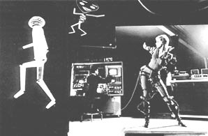
Harrison’s motion capture rigging was a prelude of things to come. The animation harness was fabricated from potentiometers and Lincoln Logs used as armatures. Manipulating the harness tied tactile movement with control voltages, making the character “dance” like the person in the harness.
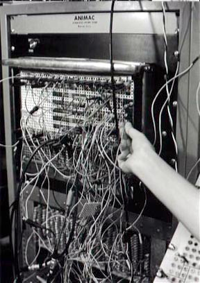
The ANIMAC was largely a proof of concept prototyped with vacuum tubes mounted on 2 by 4’s, using a Heathkit oscillator as the master clock and driving an XY oscilloscope for the display. Harrison’s company went public and was renamed Computer Image Corporation in 1969.
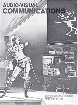
That same year ANIMAC was converted into a transistorized version. To commercialize on the scan processing experiments, the approach for moving the animated character was used instead for moving logos and high contrast graphics about the screen. The skin was “unraveled” and became small movable rasters called “flags.” The skin scanner was modified to point at the hi-contrast artwork of a logo or corporate graphic. For example, the intensity of the scanned image filled the undulating flag and was flown and spun across the surface of the screen. The multiple bone mechanism was simplified into five flag generators. The XY display was re-scanned by a video camera with 5 levers of colorization and combined with a background graphic for recording onto video tape. The new machine that incorporated all of these modifications was called Scanimate.
Scanimate allowed interactive control (scaling, rotation, translation), recording and playback of video overlay elements to generate complex 2D animations for television. In fact, most of the 2D flying logos and graphics elements for television advertising and promotion in the 1970s were produced using Scanimate systems.
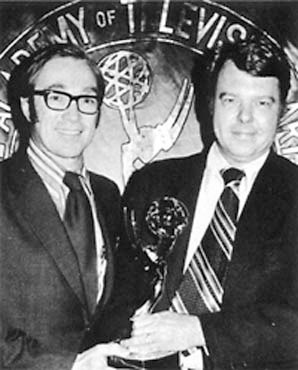
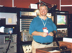
In 1972 Harrison won an Emmy award for his technical achievements. As computer graphics systems became more powerful in the 1980s, Harrison’s analog systems began to be superseded by digital CG rendered keyframe animation, and now are no longer used in production. There are several still running. Dave Sieg brought one to the SIGGRAPH 98 conference as part of a CG history exhibition.
Computer Image went on to develop a system called CAESAR, which stood for “Computer Animated Events with Single Axis Rotation.” CAESAR was targeted at moving cartoon characters’ limbs in an attempt to automate the Saturday morning cartoon production process. CAESAR used most of Scanimate’s analog processing technology with digital parameter storage on a Data General minicomputer. According to Dave Sieg:
CAESAR was never mass produced to my knowledge. A later product, System V was produced, with an improved digital computer, and it replaced Scanimate in several facilities. While at Image West, I also worked on development of a hybrid analog/digital system called VersEFx. But ultimately, the analog image quality produced by such CRT rescan systems could not compete with that of totally digital systems.
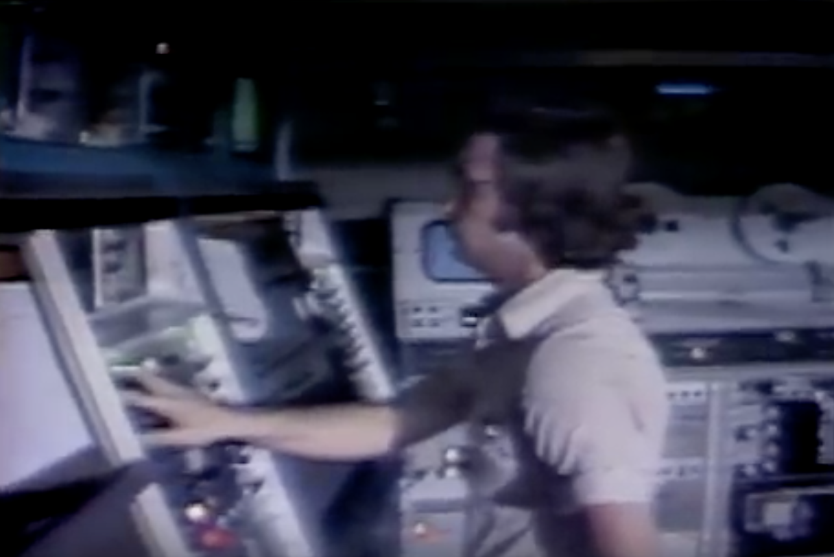
Movie 12.1 Scanimate
This short video shows the operation of the Scanimate analog graphics system
For more about Scanimate, visit Sieg’s historical web site at
http://www.scanimate.com
Dave Sieg wrote an article for the SIGGRAPH newsletter about his experiences with Scanimate as part of the SIGGRAPH 98 History Project called Scanimation in the Analog Days: Notes for an Early Animation Device
A final paper on ANIMAC was presented by Lee Harrison at the Ars Electronica Endo Und Nano Festival, in 1992
E.J. Tajchman, The Incredible Electronic Animation Machine: A Computer System Called CAESAR Is Conquering New World for Video Graphics, Videographics Magazine, Nov 1977, pp 22-24.
https://ohiostate.pressbooks.pub/app/uploads/sites/45/2017/08/IncredibleElectronic.pdf
Birger Anderson, Case Study: A Look at Video Animation, Broadcast Engineering, May 1979.
https://ohiostate.pressbooks.pub/app/uploads/sites/45/2017/08/article.pdf
Jeff Schier wrote in an essay for Ars Electronica in 1996 [1] of a visit to and conversation with Lee Harrison:
In my search for the oldest [films] I could find, I stumbled over the film of the ANIMAC, the first and the only machine of its name. “And where is the machine?” we asked eagerly. “On the dump” came the reply!
Once more we realized how hostile the industrial environment could be to a unique machine like this. How many fabulous designs are being destroyed daily just for a few cubic feet of space or the vanity of an engineer promoting his new brood. Of course Lee knew that. “They finally talked me into it!” he said sadly.
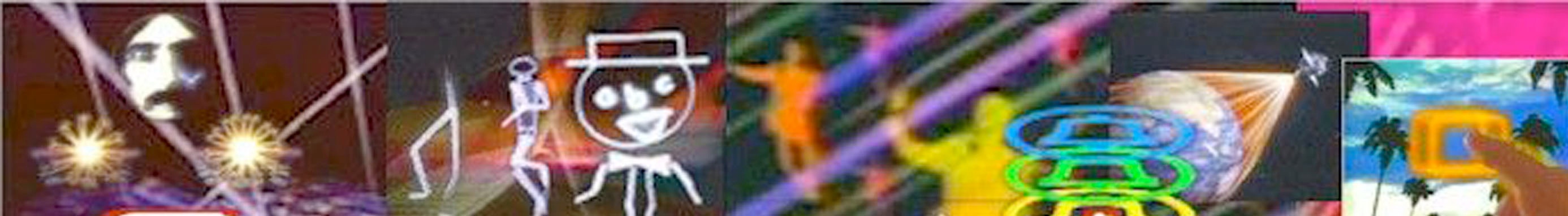
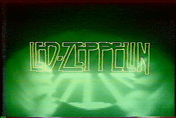
Gallery 12.1 Images from SCANIMATE
-
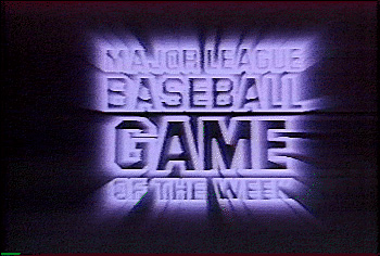
- Graphics produced on Scanimate
-
- KCOP-TV

-
- Bell Telephone
-

- 79 World Series
-
- Superbowl Graphics
